Introduction
Wacom Bamboo Fun Small
EPIA Mini-ITX Motherboard
EPIA CIR Header
Reducing Fan Speeds
Fan Voltage Calculator
|
Exploring
the CIR Header
(Consumer
Infra Red header
on EPIA, PS/2 header on EPIA-M)
WARNING:
I believe that
the information in this document is correct, but I take no
responsibility for any errors or misunderstandings, or for any damage
arising
from the use of this information. You use this information
entirely
at your own risk.
Background
The EPIA
motherboards have a 10-pin header near the PCI slot, which
is described in the manual as a CIR header for attaching a Consumer
Infra
Red module. A reference design for such a module is floating
around
on the internet, making use of a chip that even Google knows next to
nothing
about! The labelling of the pins on this reference design, and
the fact
that the self-same header on the EPIA-M boards is referred to as a PS/2
header,
gives some clue as to the actual function of the header and the
potential
for making use of it.
The pinouts are
as follows:
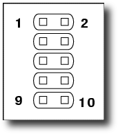
|
1
|
+5V
|
2
|
Gnd
|
3
|
Keyboard Clock
|
4
|
Keyboard Data
|
5
|
Ext Keyboard Clock
|
6
|
Ext Keyboard Data
|
7
|
Mouse Clock
|
8
|
Mouse Data
|
9
|
Ext Mouse Clock
|
10
|
Ext Mouse Data
|
WARNING: This pin numbering
corresponds to the EPIA-M viewed from above with the IDE Headers at the
bottom, and to the EPIA, viewed from above
with the IDE Headers at the top.
|
Out of the box,
the EPIA will have jumpers shorting pins 3&5, 4&6,
7&9 and 8&10. These jumpers make the connections between
the
PS/2 sockets on the backplane and the SuperIO chip on the motherboard;
removing
them allows you to capture, modify or replace these signals by
connecting
custom hardware to the header.
Connectors
At a quick
glance, the CIR header looks like the old 10-pin serial port headers
found on AT motherboards. Anyone hoping to re-use an old cable
from
this era will, however, be disappointed - the pins on the CIR header
are
spaced not at the usual pitch of 0.1 inches (2.54 mm), but at 2mm
(0.787
inches). A suitable socket housing can be obtained from Radio Spares in the UK, under
stock number 842-826
(sold in packs of 10), and some suitable crimp pins for insertion into
this
housing are sold by the hundred under stock code 842-854.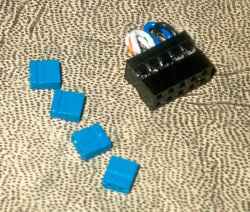
Other
considerations
There is an
internal pull-up resistor on the motherboard between each of
the Ext pins and +5v. Therefore, if you want to bypass the
external
keyboard and mouse sockets, and wire something directly to the CIR/PS2
header,
you will need to use separate pull-ups. I'm not sure of the
'correct'
value, but I've used 10kOhm resistors with no problems here.
Out of the box,
the motherboard has a set
of four extremely small and fiddly jumpers making the required
connections.
If you're going to experiement with this header, it might be wise
to
make up a loopback plug to replace these jumpers. The photograph
shows
one such loopback plug, alongside the four jumpers it replaces.
|
|